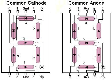
SEVEN SEGMENT DISPLAY INTERFACING WITH PIC
The Seven Segment displays are used in a digital number of systems to display the information. The Seven Segment can display one digit at a time. Thus the number of segments used depends on the number of digits in the number to be display.
Synopsis

The Seven Segment displays are used in a digital number of systems to display the information. The Seven Segment can display one digit at a time. Thus the number of segments used depends on the number of digits in the number to be display. In Seven Segment Interfacing with a PIC18F4550Microcontroller is tricky. It displays the numbers 0 to 9 and some letters, etc. The seven segment displays are made up of either LEDs (Light emitting diode) or LCDs (Liquid crystal display).The seven segments are used to display decimal and hexadecimal (0-9, A-F) values. A seven segment is cheapest option for applications requiring numeric value display as output.

Description

A Seven segment display contains seven LED ‘bars’ that can be lit up in different combinations to show the ten digits 0 to 9. In theory each ‘bar’ could be connected to PIC18F4550microcontroller output pin, but this would use up 7 of the 8 available pins.


A Seven segment consists of eight LED’s which are aligned in a manner so as to display digits from 0 to 9 when proper combination of LED is switched on. Seven segment uses seven LED’s to display digits from 0 to 9 and the eighth LED is used for the dot.

Seven segment are available in two configuration- (1) Common Anode (2) Common Cathode. Here common anode Seven segment display is used because the output current of the microcontrollerPIC18F4550is not sufficient enough to drive the LED’s, similar to the case of driving an LED. The circuit diagram shows the connections of seven Segment to the controller. The pins a to g of the Seven segment are connected to the Port P2 of the microcontroller. The common pin of the seven segment is connected to VCC. The ‘h’ has not been used, which is the dot pin of the controller.


Since the Seven segment display works on negative logic, we will have to provide logic 0 to the corresponding pin to make an LED glow. Table below shows the hex values used to display the different digits.

Common cathode

Cathode is the common pin for this type of seven segments and remaining 8 pins are left free. Here, logic low is applied to the common pin and logic high to the remaining pins.

Common anode

All the anodes of 8 LED’s are connected to the common terminal and cathodes are left free. Thus, in order to glow the LED, these cathodes have to be connected to the logic ‘0’ and anode to the logic ‘1’.

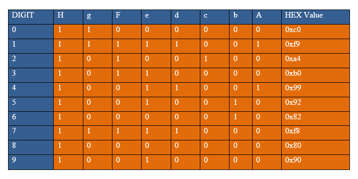
H-Segment dot led is Enable Table


When the values corresponding to the digits 0 to 9 are given on the output port, the digit gets displayed on the seven segment.

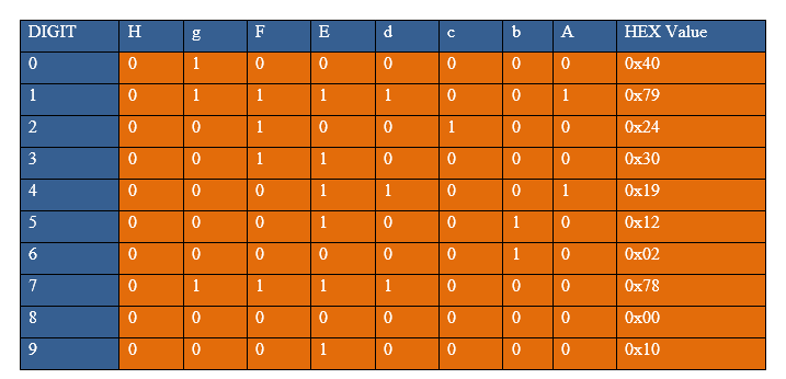
H-Segment dot led is Disable Table


Proteus design for Seven Segment interfacing with PIC


Orcad design for Seven Segment interfacing with PIC


Seven Segment interfacing with PIC

/*  Name     : main.c
 *  Purpose  : Source code for 7SEG-COMMON-ANODE Interfacing with PIC18F4550.
 *  Author   : Gemicates
 *  Date     : 2017-06-09
 *  Website  : www.gemicates.org
 *  Revision : None
 */ 
#include <htc.h>                                                          // Header file for PIC18F4550
#define _XTAL_FREQ 12000000                                               // 12MHZ
#define seg_port PORTD                                                    // To assign seg_port as PORTD

//__CONFIG(PLLDIV = 5,CPUDIV = OSC1 / 2,USBDIV = 2,FOSC = HIGH_SPEED HS); //,FCMEN = OFF,IESO = OFF,PWRT = OFF,BOR = OFF,BORV = 3,VREGEN = OFF,WDT = OFF,WDTPS = 1:32768,CCP2MX = ON,PBADEN = OFF,LPT1OSC = OFF,MCLRE = OFF,STVREN = ON,LVP = OFF,ICPRT = OFF,XINST = OFF,DEBUG = OFF,CP0 = OFF, CP1 = OFF, CP2 = OFF, CP3 = OFF,CPB = OFF,CPD = OFF,WRT0 = OFF, WRT1 = OFF, WRT2 = OFF, WRT3 = OFF,WRTC = OFF,WRTB = OFF,WRTD = OFF,EBTR0 = OFF, EBTR1 = OFF, EBTR2 = OFF, EBTR3 = OFF,EBTRB = OFF);						
#pragma config WDT = OFF
		

void delay(int msec)		                                          // delay function declaration
{															
	int i,j;
	for(i=0;i<msec;i++)
	for(j=0;j<1275;j++);

}
void main()									
{
		TRISD = 0x00;                                             // PORTD as output
		seg_port = 0xff;                                          // PORTD as input
		
	while(1)
	{
		seg_port = 0xFE;				          // 'A' segment turn on
		delay(80);                                      
		seg_port = 0xFD;				          // 'B' segment turn on
		delay(80);
		seg_port = 0xFB;				          // 'C' segment turn on
		delay(80);
		seg_port = 0xF7;				          // 'D' segment turn on
		delay(80);
		seg_port = 0xEF;				          // 'E' segment turn on
		delay(80);
		seg_port = 0xDF;				          // 'F' segment turn on
		delay(80);  
		seg_port = 0xBF;				          // 'G' segment turn on
		delay(80);
		seg_port = 0x7F;				          // 'H' segment turn on
		delay(100);
		
		// Default 'H' segment turn OFF
		seg_port = 0x40;				          // Display '0'
		delay(80);
		seg_port = 0x79;				          // Display '1'
		delay(80);
		seg_port = 0x24;				          // Display '2'
		delay(80);
		seg_port = 0x30;				          // Display '3'
		delay(80);
		seg_port = 0x19;				          // Display '4'
		delay(80);
		seg_port = 0x12;				          // Display '5'
		delay(80);
		seg_port = 0x02;				          // Display '6'
		delay(80);
		seg_port = 0x78;				          // Display '7'
		delay(80);
		seg_port = 0x00;				          // Display '8'
		delay(80);
		seg_port = 0x10;				          // Display '9'
		delay(100);
		
		// Default 'H' segment turn ON
		seg_port = 0xC0;				          // Display '0'
		delay(80);
		seg_port = 0xF9;				          // Display '1'
		delay(80);
		seg_port = 0xA4;				          // Display '2'
		delay(80);
		seg_port = 0xB0;				          // Display '3'
		delay(80);
		seg_port = 0x99;				          // Display '4'
		delay(80);
		seg_port = 0x92;				          // Display '5'
		delay(80);
		seg_port = 0x82;				          // Display '6'
		delay(80);
		seg_port = 0xF8;				          // Display '7'
		delay(80);
		seg_port = 0x80;				          // Display '8'
		delay(80);
		seg_port = 0x90;				          // Display '9'
		delay(100);
	}
}

Error message here!

Show Error message here!


Forgot your password?

Error message here!

Send OTP

Error message here!

Show Error message here!


Lost your password? Please enter your email address. You will receive a password you Need.

Send Error message here!


Back to log-in

Close