SERVO MOTOR INTERFACING WITH AVR
A servo motor is an electric device used for precise control of angular rotation. It is used where precise control is required, like in case of control of robotic arm.
Synopsis

A servo motor is an electric device used for precise control of angular rotation. It is used where precise control is required, like in case of control of robotic arm.It consists of a suitable motor with control circuitry for precise position control of the motor shaft.It is a closed loop system.

The rotation angle of the servo motor is controlled by applying a PWM signal to it.

By varying the width of the PWM signal, we can change the rotation angle and direction of the motor. For more information about Servo Motor and how to use it, refer the topic Servo Motor in the sensors and modules section.

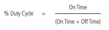
For information about PWM in ATmega16, refer the topic PWM in ATmega16 in the ATmega inside section.
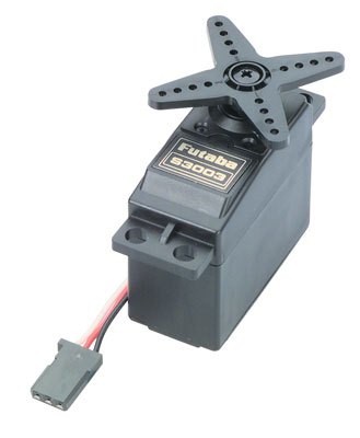
Description

Servo refers to an error sensing feedback control which is used to correct the performance of a system. Servo or RC Servo Motors are DC motors equipped with a servo mechanism for precise control of angular position. The RC servo motors usually have a rotation limit from 90° to 180°. Some servos also have rotation limit of 360° or more. But servos do not rotate continually. Their rotation is restricted in between the fixed angles.

SG90 servo motor practical duty cycle time for -90° to +90 rotation.

At ~0.52ms duty cycle we get shaft position at -90° of its rotation.

At ~1.4ms duty cycle we get shaft position at 0° (neutral) of its rotation.

At ~2.4 ms duty cycle we get shaft position at +90° of its rotation.

Servo Control

The servo motor can be moved to a desired angular position by sending PWM (pulse width modulated) signals on the control wire. The servo understands the language of pulse position modulation. A pulse of width varying from 1 millisecond to 2 milliseconds in a repeated time frame is sent to the servo for around 50 times in a second. The width of the pulse determines the angular position.

For example, a pulse of 1 millisecond moves the servo towards 0°, while a 2 milliseconds wide pulse would take it to 180°. The pulse width for in between angular positions can be interpolated accordingly. Thus a pulse of width 1.5 milliseconds will shift the servo to 90°.

It must be noted that these values are only the approximations. The actual behavior of the servos differs based on their manufacturer.


A sequence of such pulses (50 in one second) is required to be passed to the servo to sustain a particular angular position. When the servo receives a pulse, it can retain the corresponding angular position for next 20 milliseconds. So a pulse in every 20 millisecond time frame must be fed to the servo.

Most servo motors can rotate about 90 to 180 degrees. Some rotate through a full 360 degrees or more. Servos that can rotate 360 degrees are required mainly for building RC helicopters.

Most commonly available servos have a three wire connector. One wire supplies positive DC voltage – usually 5 to 6 volts. The second wire is for voltage ground, and the third wire is the signal wire. The receiver “talks” to the servo through this wire by means of a simple on/off pulsed signal. In this tutorial, we will be using the servo which have a three wire connector i.e. power, ground and control. Also every servo will have different torque, speed and response time rating. Before purchasing, please check the ratings based on your applications. Unlike other motors, Servo motors don’t require any driver. When a PWM signal is applied to its control pin the, the shaft rotates to a specific angle depending on the duty cycle of the pulse. PWM stands for pulse width modulation. It is basically a modulation technique, in which the width of the carrier pulse is varied in accordance with the analog message signal. As described above, it is commonly used to control the power fed to an electrical device, whether it is a motor, an LED, speakers, etc.

The main thing that is important in the PWM is the duty cycle. It’s defined as


This is just a theoretical formula. Practically, imagine a motor that requires 5v to run at certain RPM. Let the RPM be 300. If the voltage is applied 5v then motor will take 300rounds per minute. However when the voltage applies is 2.5v the motor will take only 150 rounds per minute. Again if the voltage applied is 3.75v, the motor will run at 225 rpm. To achieve this, we use PWM. Let’s say the microcontroller is running at 5v.

At a certain time you apply stream of pulses which have equal turn off and turn on time i.e. they have a 50% duty cycle. The pulses are fed to the motor. However, since the duty cycle is 50% the motor will have an input of 2.5V instead of 5V due to continuously being switch on and off with equal time interval. In general the ratio of input voltage to the motor and the output of the microcontroller will be equal to duty cycle ration that is ratio of time the pulses are on and the total time period. For ex if the duty cycle is 75% then duty cycle ratio is 75/100 and that will be equal to ratio of input to motor and output of microcontroller. Since the output of microcontroller is 5v, the input to the motor will be 3.75V.

Proteus design for Servo Motor interfacing with AVR


Orcad design for Servo Motor interfacing with AVR


Servo Motor interfacing with AVR

/*  Name     : main.c
 *  Purpose  : Source code for Servo Motor interface with ATMEGA16.
 *  Author   : Gemicates
 *  Date     : 2017-09-07
 *  Website  : www.gemicates.org
 *  Revision : None
 */

#ifndef F_CPU
#define F_CPU 8000000UL        // 8 MHz clock speed
#endif

#include <avr/io.h>
#include <util/delay.h>

int main(void)
{
    DDRC = 0x01;               // Makes RC0 output pin
	PORTC = 0x00;
	while(1)
    {
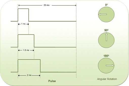
                               // Rotate Motor to -90 degree
	   PORTC = 0x01;
	   _delay_us(1000);
	   PORTC = 0x00;
	   
	   _delay_ms(2000);
	   
	                       // Rotate Motor to 0 degree
	   PORTC = 0x01;
	   _delay_us(1500);
	   PORTC = 0x00;
	   
	   _delay_ms(2000);
	   
	                       // Rotate Motor to +90 degree
	   PORTC = 0x01;
	   _delay_us(2000);
	   PORTC = 0x00;
	   
	   _delay_ms(2000); 
    }
}

Error message here!

Show Error message here!


Forgot your password?

Error message here!

Send OTP

Error message here!

Show Error message here!


Lost your password? Please enter your email address. You will receive a password you Need.

Send Error message here!


Back to log-in

Close