LED INTERFACING WITH PIC
This function is very basic operation of taking an output from the microcontroller PIC18F4550. It demonstrates the principle behind interfacing LEDs with PIC microcontroller. It is continuously ON and OFF function at a predefined time delay output.
Synopsis

This function is very basic operation of taking an output from the microcontroller PIC18F4550. It demonstrates the principle behind interfacing LEDs with PIC microcontroller. It is continuously ON and OFF function at a predefined time delay output. They are very cheap and easily available in a variety of shape, size and colors. They find multiple applications as indicators during experimentations to check the validity of results at different stages.

An LED is basically a p-n junction diode which emits light energy when adequate voltage is given. It has found its way to the low power display systems recently. It is the most commonly used indicator lights in all the applications. Ever since it’s wide spread use as reliable electronic component. LED bulbs are available in different colors. Earlier LEDs made use of the infra-red wavelength and such LEDs are used even these days in remote-control circuits. LED bulbs making use of the ultra violet wavelength is also available in the market.

As discussed earlier, LEDs are present in many electronic devices including lamps, digital clocks and incandescent bulbs. A very popular application of LED is a seven segment display system. The advantages of LEDs over normal incandescent lights include robustness, faster switching, lower energy consumption and small size.

Description

PIC18F4550, which belongs to the family of PIC18XX series of microcontrollers, is very commonly used by a large community of hobbyist and engineers. Its simplicity and ease of programming with inbuilt features easily makes its position in the top preferred list of microcontroller for both beginners and advanced user.


LED is by far the most widely used means of taking output. They find huge application as indicators during experimentations to check the validity of results at different stages. They are very cheap and easily available in a variety of shape, size and colors.

The principle of operation of LEDs is simple. The commonly available LEDs have a drop voltage of 1.7 V and need 10 mA to glow at full intensity. The following circuit describes “how to glow a led”.

The value of resistance R can be calculated using the equation,

R= (V-1.7)/10 mA. Where V is the input voltage.

Since most of the controllers work on 5V, so substituting V= 5V, the value of resistance comes out to be 330 ohm. The resistance 220 ohm, 470 ohm is commonly used substitute in case 330 ohm is not available.

The PIC18F4550 microcontroller can sink (“absorb”) or source (“give out”) a small amount of current, which means that an LED can be connected directly to the output pin. A series resistor (value 330R) is also required to limit the current.


PIC18F4550 has a total of 35 I/O (input-output) pins which are distributed among 5 Ports. The following table shows the names and numbers of I/O pins of these 5 ports:


TRISX (TRI STATE)

This is a data direction register which sets the direction of each port pin as input or output.

PORTX

This register stores the input level of pins (High or Low). When a pin configured as input, the input signal from external source is read from PORTX register.

LATX

This is output latch register. The data which has to be sent to external hardware as output is stored in LATX register.

Proteus design for LED interfacing with PIC


Orcad design for LED interfacing with PIC


LED interfacing with PIC

/*  Name     : main.c
 *  Purpose  : Source code for LED Interfacing with PIC18F4550.
 *  Author   : Gemicates
 *  Date     : 2017-06-10
 *  Website  : www.gemicates.org
 *  Revision : None
 */
#include <htc.h>                   // Header file for PIC18F4550
#define _XTAL_FREQ 12000000        // 12MHZ

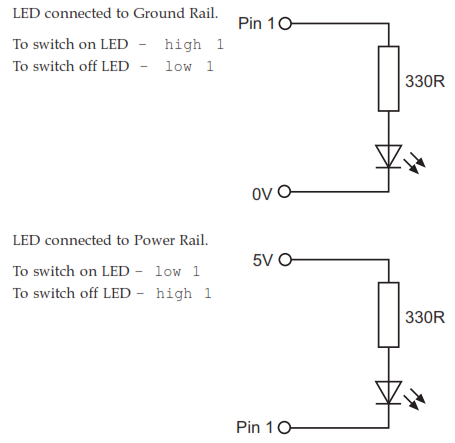
#define LED PORTB                  // PORTB as Output
#define LED9 PORTCbits.RC0         // PORTC as Output
#define LED10 PORTDbits.RD0        // PORTD as Output
#define SW PORTDbits.RD1           // PORTD as Output

/**********CONFIGURATION BITS SETTING**********/
#pragma config FOSC = HSPLL_HS     // Using 20 MHz crystal with PLL
#pragma config PLLDIV = 5          // Divide by 5 to provide the 96 MHz PLL with 4 MHz input
#pragma config PBADEN = OFF
#pragma config CPUDIV = OSC1_PLL2  // Divide 96 MHz PLL output by 2 to get 48 MHz system clock
#pragma config FCMEN = OFF         // Disable Fail-Safe Clock Monitor
#pragma config IESO = OFF          // Disable Oscillator Switchover mode
#pragma config PWRT = OFF          // Disable Power-up timer
#pragma config BOR = OFF           // Disable Brown-out reset
#pragma config WDT = OFF           // Disable Watchdog timer
#pragma config MCLRE = ON          // Enable MCLR Enable
#pragma config LVP = OFF           // Disable low voltage ICSP
#pragma config ICPRT = OFF         // Disable dedicated programming port (only on 44-pin devices)
#pragma config CP0 = OFF           // Disable Code Protection Bit
/************************************************/


void main()									
{
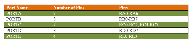
    TRISB = 0x00;                  // PORTB as Output       
                                 
    TRISC = 0xfe;                  // RC0 as Output
    TRISD = 0xfe;                  // RD0 as Output
	
					
    while(1)			   // Loop executed infinite times		   			
    {
	if(SW==0)                  // LED turn OFF using Push Button
        {
         LED10 = 1;                // LED OFF Condition
        }                       
	if (SW==1)                 // LED turn ON using Push Button           
	{
            LED10 = 0;             // LED ON Condition    	
	}
	LED = 0xff;	           // LED OFF Condition	                  
        __delay_ms(50);            // delay of 50ms              
	LED = 0x00;	     	   // LED ON Condition                 
        __delay_ms(50);            // delay of 50ms             
	
	LED9 = 0;                  // LED ON Condition      
	__delay_ms(50);            // delay of 50ms              
	LED9 = 1;                  // LED OFF Condition              
	__delay_ms(50);            // delay of 50ms 
    }	
}	


Error message here!

Show Error message here!


Forgot your password?

Error message here!

Send OTP

Error message here!

Show Error message here!


Lost your password? Please enter your email address. You will receive a password you Need.

Send Error message here!


Back to log-in

Close